Optical Film Slitting Guide: Cleanroom Setup, Tension & Static Control
Cutting expensive film materials like PET, TAC, and screen display polarizers carries constant risks of wasting product. Floating dust, static pull, and rough edge quality can ruin delicate rolls of plastic quickly. However, you can improve your film cutting process by using correct cleanroom working methods. Getting good results requires tested room cleanliness, active static control, steady web tension management, and carefully designed machinery. This practical guide helps factory engineers fix real cleanroom cutting problems during daily machine operations. You can remove surface dirt, meet strict accuracy needs, and protect delicate film bases. Using a dedicated optical film Slitting Machine gives you the extreme accuracy required for high-profit factory jobs.
Key Takeaways
-
Run your film cutting machine in ISO Class 5 to Class 7 cleanrooms to keep floating dust from ruining your products.
-
Put working ionizer bars close to the unwind spindle and cutting blades to remove surface static.
-
Use closed-loop tension control systems to keep optical surfaces from stretching or warping during fast speed changes.
-
Put in differential friction shafts to keep an even winding pull on plastic rolls that have different thicknesses.
-
Pick shear slitting instead of razor cutting to get smooth edges and create less plastic dust.
-
Set the cutting blade angles to 45 degrees so the physical cutting forces spread out evenly.
-
Add fast camera systems to find moving sheet surface flaws right away.
Cleanroom Setup for Optical Film Slitting
High-yield output requires strict environmental rules while cutting precision films. Dust falling on clear plastic film causes immediate product rejection later. You must keep air pure across every single web handling step. Dedicated cleanroom layouts safeguard release liners and optical films from environmental ruin. Proper isolation stops severe tiny-dust buildup on delicate material rolls. Precision cutting jobs need spotless workspaces to deliver perfect product quality.
ISO 14644-1 Airflow & Environmental Controls
The ISO 14644-1 rule sets necessary air purity levels for cleanroom factories. You must set up an ISO Class 5 to Class 7 room to process clear films safely. Many optical factories run inside ISO 7/Class 10,000 or ISO 8/Class 100,000 cleanrooms to limit dust counts. Special rooms use positive air pressure to stop dirty outside air from entering open doors. Constant air movement shields fragile films throughout production runs. Fast air change rates clear floating dust quickly, keeping daily work areas clean. Correct pressure levels block outside dirt from reaching cutting zones. Sending clean air continuously removes floating dust, securing high yield rates for sensitive optical films. Controlled air currents sweep away stray particles before dust settles.
Mitigating Airborne Particle Contamination
Stopping airborne dust requires powerful air filters and disciplined worker rules. Unprotected workers are the biggest source of dirt in clean rooms. You must enforce strict suit rules and limit extra movements near open film paths. Clean air supply setups constantly remove room dust, saving sensitive material rolls from damage. Moving less reduces air mixing around open film lines. Safe workplace rules stop floating dust movement, protecting delicate film surfaces from continuous air dirt.
HEPA and ULPA Air Filtration Setup
High-efficiency particulate air (HEPA) and ultra-low penetration air (ULPA) filters clear the room air continuously. These advanced filter networks catch microscopic dust before air hits the cutting section. Fast air change rates blow away skin bits and fabric threads quickly. Sealed filter walls keep overall air clean and balance room pressure. Recirculated air passes constantly through extra filter banks to hold high room standards. Dedicated filter units remove tiny dust, preventing severe film damage during roll unwinding.
Laminar Airflow Vectoring at the Slitting Zone
Place high-speed straight-airflow hoods right above the active cutting blades. Direct downward air pushes created dust down away from the moving film web. Air streams protect the cutting area, shielding sensitive film surfaces from floating dirt. This focused air direction keeps the web clean during fast film movement. Smooth air hoods stop messy air swirls near sensitive blade units during fast runs. Direct air streams protect continuous material sheets in modern optical film slitting operations. Positive air barrier methods prevent surface dirt near open film paths.
Roller Hygiene & Molecular Contamination
Physical dirt is not the only threat during film cutting. Chemical fumes and transferred oils make invisible surface flaws on materials. You must fight chemical dirt through smart part choices and steady cleanup habits. Keep roller surfaces clean to prevent micro-scale surface damage and keep edges pure. Set maintenance routines stop oil transfers to clear film layers. Good cleaning prevents hidden roller dirt from ruining whole factory runs.
Non-Outgassing Roller Material Selection
Choose low-fuming machine parts across the entire film path. Standard rubber rollers release chemical fumes that ruin optical coatings. You must install special non-fuming rubber rollers to protect every delicate surface. These stable roller materials stop residue transfers, removing fine surface scratches during fast spinning. Soft touch rollers hold fragile web structures without making chemical marks. Clean parts preserve coating safety across the full web width while running the cutting process. Low-fuming surfaces stop microscopic film deposits on delicate top layers.
Active Web Cleaning Roller Maintenance
Keep strict roller cleaning habits to shield moving material rolls. Machine workers must wear lint-free gloves during all manual work. Use soft-tipped tools and safe cleaning liquids during regular maintenance stops. Solvent wipes must clean off built-up plastic dust without hurting roller coatings. Continuous web cleaning systems wipe the film before blade contact, removing fine dirt before cutting begins. Clean contact rollers prevent micro-scratches on clear layers. Proper care keeps machines clean and stops accumulated dirt on finished roll products. Dedicated cutting hardware runs continuously inside certified rooms to keep film surfaces clean before cutting. Special slitting machines keep stable roll alignment while meeting cleanroom standards. Regular checkup schedules prevent dirt buildup on important guide rollers in professional optical film slitting setups. Advanced slitting machines use smooth surfaces to speed up daily cleaning, while better cleaning habits raise room purity.
Static Charge Control in Web Handling
Unwinding high-speed optical web rolls generates powerful electrostatic forces. You must control static electricity to maintain product cleanliness and stop costly scrap during film conversion.
Electrostatic Attraction Mechanics
Fast roll unwinding builds high friction on your machinery line. Insulating plastic webs generate rapid surface charges during continuous motion. You can track several key causes of static buildup during web movement:
-
Interlayer separation creates rapid charge buildup during roll unwinding.
-
High-speed contact with friction-heavy guide rollers generates static constantly.
-
Dry air prevents natural charge dissipation across the moving web.
High static levels create an invisible pull force. This magnetic-like attraction pulls the moving film toward nearby metal machine frames. Web movement unstable under this force causes severe alignment tracking issues. Strong electrostatic fields attract airborne dust directly to the material surface. Particle contamination settles quickly on the plastic sheet. Unchecked static pulls micron-sized dust and metal debris onto the roll. These trapped particles cause severe surface scratches during rewinding. You must neutralize static early to maintain surface cleanliness and stop material contamination.
Active Ion Bar Placement Strategies
Active ionizer bars eliminate static by flooding the web with positive and negative ions. You need strategic bar placement to maintain charge control throughout high-speed slitting operations.
Continuous ionization preserves process cleanliness across the entire slitting line. Focused air ionization neutralizes high voltage charges without touching delicate optical coatings.
Unwind Zone Static Dissipation
You must target high static charges at the master roll unwind station. Unwinding film generates peak voltages right at the separation point. Mount active ionizer bars immediately down-line from the primary unwind spindle. Position the ionization emitters across the full web width.
High unwinding speeds create continuous friction across primary support rollers. Neutralizing the static charge early stops airborne particle attraction before the web travels deeper into the slitting machine. Continuous charge removal keeps raw optical sheets completely pure.
Slitting Point Ionization Positioning
Blade contact creates localized static spikes during web slitting. You must position active ionizer bars upstream of slitting knives at a distance of 25 mm to 50 mm from the cutting zone. Keep the ionizer bar at least 50 mm away from roller contact points.
Neutralizing charges right at the knife unit prevents web contamination on the delicate film. Proper placement guarantees edge cleanliness and maintains process consistency. You also need dedicated ion bars right ahead of rewind stations. Neutralized web layers prevent contamination entrapment inside finished optical film rolls.
Equipment Grounding and Substrate Discharge
Active ionization requires complete machinery grounding to protect your sensitive surface materials. Connect all slitting equipment frame components directly to earth ground. Low-resistance grounding paths bleed off stray electrical charges safely into the cleanroom ground grid.
Direct machine grounding prevents sudden spark discharges between rollers and delicate optical substrates. Safe static dissipation shields your clear film from physical surface damage. Proper electrical grounding prevents surface contamination on every finished material roll.

Precision Web Tension Management
Dynamic tension changes create severe optical distortion during web handling. Uncontrolled pull forces cause surface scratches, edge deformation, and core crushing. You must maintain strict control over dynamic web forces to protect sensitive surface layers like PET and TAC. Precision web management keeps web pull stable during rapid speed changes. Proper tension adjustments preserve film flatness across every operating shift.
Closed-Loop Tension Control Systems
Automatic tension control holds constant pull forces along the whole material web in high-speed slitting operations. The control unit adjusts motor torque instantly as your machine speeds up or slows down. Proper tension management stops material stretching and guarantees high precision throughout production. Reliable system controls prevent sudden tension spikes on fragile film webs.
Dynamic Load Cell Feedback Loops
Load cells continuously measure web tension and send real-time force data to the system controller. You should command drive motors in torque mode with scaling directly from load cell feedback. This setup avoids complex nested position loops and guarantees clean pull forces during speed changes.
Industry data shows that when tension variation is kept within ±5%, production yield often exceeds 95%. However, if fluctuations reach ±15%, yield can drop below 80%.
Converting high-value substrates demands exceptional precision. Upgrading a production line from dancer feedback to a closed-loop system with load cell feedback reduces tension variation from ±12% to ±3%. This improvement increases yield from 88% to 97% and cuts equipment downtime by 40%. The load cell loop instantly corrects force deviations, eliminating web distortion across every slitting run.
Taper Tension Calculations for Optical Cores
Rewind roll diameters grow larger during continuous winding. Larger roll diameters require lower web tension to prevent high internal pressures. You must calculate and apply a torque taper coefficient between 0.5 and 0.7. This gradual tension reduction prevents core crushing and maintains structural consistency.
Proper taper calculations reduce web pull as the roll diameter expands. Controlled winding force protects inner core layers from severe compression. Consistent winding pressure guarantees uniform roll hardness from the inner core to the outer layer.
Differential Friction Shaft Rewinding
Optical web rolls often exhibit slight thickness variations across their width. Standard solid rewind shafts distribute tension unevenly across multiple narrow strips during the slitting process. You can resolve this balance issue by using differential friction shafts on your slitting line.
Differential friction shafts operate at a slight over-speed of 1% to 3%. Internal pneumatic friction rings allow individual slit rolls to slip independently along the shaft. This independent slipping action maintains uniform pull force on every slit strip, even when roll diameters vary slightly across all narrow slitting lanes.
Telescoping is a classic symptom of inadequate tension control combined with a lack of differential slipping.
Independent roll slipping eliminates uneven web pulling across the shaft. Uniform winding tension stops material layers from shifting sideways under lateral pressure. Proper friction shaft operation protects material quality and delivers superior slitting performance.
Preventing Scratches, Wrinkles, and Telescoping
Eliminating visual defects requires precise mechanical choices across the web path. You must keep overall web tension in a low range below 30 N/m to prevent film stretching and wrinkles. Small wrap angles on guide rollers reduce contact friction on every optical layer. Synchronized active drive rollers eliminate sliding friction, which stops optical scratches.
Proper tool setup protects the physical slit edge during operation. You must set slitting blade angles below 30° and adjust blade gaps strictly between 0.01 mm and 0.03 mm. Precise knife positioning minimizes cutting resistance and stops severe edge burrs. Precise edge alignment prevents web distortion while maintaining continuous web control.
Use these practical methods to eliminate material defects on fragile optical webs:
-
Apply light-touch contact rollers at pressures between 0.1 bar and 0.5 bar to push out trapped air without causing surface scratches.
-
Place active static neutralizers right along the web path to eliminate static attraction and stop wrinkles.
-
Install razor blades inside grooved support rollers to stabilize the moving web and avoid scratches.
Maintaining continuous force stability stops inner roll pressure from pushing film layers outward during winding. Dynamic tension management prevents unwanted material deformation across every processing stage. Stable web guidance delivers exceptional finished-roll consistency across long conversion runs. You protect expensive optical substrates, eliminate scrap, and maximize factory output through accurate tension control.
Blade Selection & Shear Slitting Mechanics
Razor vs. Shear Cut Mechanics
Pick the right cutting method to shield delicate film rolls when slitting. Razor cutting uses sharp blades mounted in air or inside slotted rollers. This easy process cuts flexible plastics and thin films well. Yet, one blade touching the sheet makes rubbing forces that boost tiny dust.
Shear cutting relies on top and bottom round knives cutting like smooth scissors. This steady method cuts thick films, paper, layers, and foils. You get clean sides and tiny dust using shear blades during exact slitting.
|
Aspect |
Razor Slitting |
Shear Slitting |
|---|---|---|
|
Cutting mechanism |
Uses sharp razor blades in air or in grooves |
Uses male and female circular knives in scissor action |
|
Material suitability |
Suited for thin films, light foils, delicate substrates |
Suitable for films, paper, laminates, textiles, foils |
|
Edge quality |
Precision cutting on light substrates |
Superior edge quality with clean, precise edges |
|
Edge debris |
Generates more debris from single-blade contact |
Minimal dust generation with less edge debris |
Minimizing Slit Edge Debris
Dust on cut edges ruins plastic surfaces later in factory processing steps. Fine plastic bits slide fast between clean film layers while winding rolls. You must control mechanical cutting forces to shield final product purity.
Smart cutting methods keep side edges smooth without fuzzy threads or rough burrs. Careful knife handling stops tiny edge cracks while running the slitting process. Keeping machines in top shape ensures steady sheet flow and keeps optical layers pure.
Slitter Blade Geometry & Alignment Angle
Use special blade metals to get exact cuts on fast factory slitting lines. Heavy daily cutting lines need Tungsten Carbide knives to stop fast tool wear. Very thin optical films under 30µm need Diamond-Coated blades setting an exact limit of ±0.01mm. Stainless Steel options stop tiny chips while slicing clear sheet layers.
|
Aspect |
Recommendation |
Note |
|---|---|---|
|
Blade Angle |
45° installation |
Distributes cutting force evenly; reduces edge stretch |
|
Blade Material |
Tungsten Carbide, Stainless Steel, or Diamond-Coated |
Select based on line intensity and material thickness |
|
Coating |
TiN/TiAlN, Ceramic, Teflon, or Mirror-Polished |
Reduces adhesive transfer, friction, and debris |
Proper blade angle setups stop plastic from rubbing along the metal side wall. Setting blades at a 45° angle spreads cutting force evenly across film channels. Special blade coatings block glue buildup, keeping product edges clean for long runs.
Vacuum Dust Extraction Integration
Active vacuum tools remove floating dust right at the open cutting point. Mixing air suction with ionized blowing keeps overall room purity high.
-
Vacuum Systems: Create low-pressure zones to draw loose particles into collection units.
-
Air Knives: Deliver high-velocity air sheets to blow off surface particles.
-
Brush Rollers: Sweep away loose fibers using rotating bristled cylinders.
-
Ionizing Bars: Neutralize static electricity to loosen trapped surface debris.
Built-in vacuum hoods pull fine dust away before specks land on clear sheets. This active tool setup stops dust damage across your whole film slitting line.
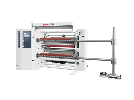
Sanhui Machinery Optical Film Slitting Machine Solutions
Sanhui Machinery operates as a trusted slitting machine manufacturer delivering one-stop slitting and rewinding solutions for industrial converters worldwide. You can process high-precision optical films, plastic films like PET, OPP, and PVC, and sensitive electronic substrates effortlessly. Installing a dedicated optical film slitting machine elevates your factory yield significantly.
Specialized machine configurations solve daily operational bottlenecks during optical film slitting processes. You can prevent costly web defects while keeping production environments clean. Converting delicate roll products requires specialized optical film slitting equipment that preserves surface purity across every processing cycle.
High-Precision Tension & Edge Correction Technology
A fully automatic closed-loop tension control system maintains constant web pull across all velocity changes. The integrated EPC edge correction device aligns moving material sheets automatically. This precision system prevents web deviation and protects every slit edge.
You can select flexible speed settings up to high-speed models reaching 800m/min. Stable tension management maintains running consistency throughout demanding slitting runs. Smooth driving mechanisms ensure optimal speed consistency while protecting fragile web structures during fast slitting cycles.
Cleanroom-Compatible Slitter Engineering
Sanhui builds converting equipment using compact non-contaminating body structures. Sealed machine housing components eliminate airborne particle traps and prevent severe particle contamination across active web zones. You protect delicate optical surfaces from ambient factory contamination and particulate buildup.
Engineers integrate specialized structural elements to support strict cleanroom environments:
-
Clean room compatible structure enables easy roll cleaning
-
A new type of expansion chuck minimizes particle generation problems, achieving high-accuracy cleanliness
This engineering approach maintains environmental cleanliness during long processing shifts. Non-fuming machine surfaces limit local contamination while protecting fragile material layers.
Ultra-Precise Slitting Accuracy (±0.1mm)
High-rigidity cutter assemblies provide high precision during continuous material slitting operations. The specialized optical film slitting machine satisfies your strict precision requirements for sensitive substrates. You achieve a clean burr-free edge profile on every narrow strip.
The machine delivers ultra-precise slitting accuracy reaching ±0.1mm. Accurate tool positioning prevents web tears and preserves precise edge alignment. Careful knife positioning eliminates micro-cracks along the cut edge boundary while maintaining exceptional slitting precision.
Rewind Flatness Control (≤0.5mm)
Advanced differential friction shafts preserve physical web geometry on finished output rolls. You achieve superior rewinding end face flatness within ≤0.5mm during continuous slitting operation. This mechanical control guarantees overall finished-roll consistency across wide rolls.
The controlled winding process delivers wrinkle-free rolls without physical scratches. Selecting a premium optical film slitting machine enhances operational cleanliness during every slitting performance. Continuous static control prevents ambient dust attraction and stops surface scratches on every slit edge.
Quality Assurance & Edge Inspection Protocols
In-Line Surface Defect Detection Systems
You must check film quality constantly during fast factory runs. Smart vision cameras scan every moving sheet while your machine cuts. High-speed line-scan camera setups perform real-time 2D and 3D checks across the entire web width. These optical tools track product quality at high running speeds up to 600 m/min. Automated camera networks flag subtle machine-direction surface scratches right away. Smart image software catches floating dust and room dirt before rolls roll back up. Sensitive digital sensors group surface flaws by size and shape quickly. Instant alerts tell workers to adjust tension controls along your optical cutting line. Continuous optical monitoring stops damaged film parts from reaching final customer rolls.
Special optics spot surface marks across both wet and dry optical coatings. Solid State Laser Reflection (SSLR) tools run at speeds over 30 m/min to scan clear sheets. Compact self-aligning sensors inspect raw film down to 1.5 μm submicron levels. This extreme accuracy maintains surface purity on sensitive PET and TAC layers. Finding flaws early stops deep scratches from ruining entire film lots. Automated scanning keeps work areas clean along delicate processing lines. Focused lighting units reveal tiny surface pinholes without touching fragile plastic sheets. Reliable optical signals send continuous data right to automatic record systems.
Cross-Sectional Slit Edge Quality Auditing
You need strict testing rules to check every cut film edge. Shear knives must cut clean side walls without making micro-cracks or burrs during automated cutting runs. Workers take sample strips after finishing each fast film slitting job. High-power optical microscopes scan side edge profiles to check exact shape accuracy. Checking physical cut edges ensures high accuracy across every narrow strip. Smooth blade contact protects overall film strength, preventing loose plastic dust. Lab technicians log exact side measurements to verify blade distance setups. Regular edge checks help you spot knife wear early before edge damage lowers factory output.
Keeping cut edges smooth stops plastic dust from shedding inside completed rolls. Side dust ruins optical coatings while shipping film products to customers. Regular edge cleanliness checks confirm that vacuum suction setups catch fine plastic dust. Checking edge shapes keeps roll winding steady across wide factory runs. Consistent side quality protects sensitive coatings and keeps raw films clean. Inspecting side wall shapes proves blade angles stay correct during fast slitting jobs. Proper test habits ensure high factory output for every finished roll product. Quality control teams check edge straightness using special software tools. Tough quality tests protect delicate optical films from sudden factory breakdown risks.
Getting great results when cutting optical film takes strict cleanroom cleaning, active static control, steady pull management, and exact blade alignment. You protect delicate materials from surface dirt and static pull by using smart sheet handling methods daily.
Strong factory equipment from Sanhui Machinery improves your production line cutting jobs with automatic pull control systems and sharp blade setups. This dependable machinery holds ±0.1mm cutting accuracy, stopping expensive sheet flaws while boosting cleanroom factory output.
Check your current cleanroom setup today to stop material waste during cutting runs. Contact Sanhui Machinery right now to build a custom optical film slitting machine for your exact edge controls and factory needs.
FAQ
What cleanroom class standard do you need for processing clear optical substrates?
You should work inside an ISO Class 5 to Class 7 room following ISO 14644-1 rules. These safe spaces stop tiny dust dirt on delicate materials, clear backing sheets, and sensitive coated layers during processing.
How does automatic closed-loop tension control improve optical film slitting?
Automatic pull control holds steady web force through all speed changes. This tech stops surface scratches, sheet stretching, and web twisting. Keeping dynamic pull steady guarantees smooth work and shields your delicate PET or TAC materials.
What slitting method minimizes debris on delicate films?
Shear cutting makes less dust than razor blades. Using top and bottom round knives like smooth scissors creates clean cuts. You get neat side shapes while stopping tiny cracks along the web edge.
What accuracy and flatness tolerances can you achieve with dedicated equipment?
You can hit amazing accuracy up to ±0.1mm. Modern differential friction shafts also keep finished roll side flatness within ≤0.5mm. Strict limits stop web twisting and prevent roll slipping across long factory runs.
Where should you position active ionizer bars along the material path?
Put active ion bars right after the main unwind shaft to remove static early. You must also place ionization bars 25 mm to 50 mm before blade sets to clear static spikes before cutting sheets.
Why is differential friction shaft rewinding essential for optical films?
Film sheets often show small thickness changes across their width. Differential friction shafts let single rolls slide on their own. This sliding action keeps even pull across all lanes, stopping visual distortion and roll shifting.
What maximum speed can high-speed optical film slitting machine models reach?
Fast optical film slitting machines reach work speeds up to 800m/min. You can change speed controls easily while trusting closed-loop systems to keep product purity and sheet flatness.
How do specialized blade geometries protect the cut edge?
Setting blade setup angles at 45° spreads cutting forces evenly. Special tool layers like TiN or Ceramic lower rub forces and stop glue sticking, keeping clean sheet edges through long daily runs.